Motorcycle Light Circuit (part 2)
- Andrew Asuelime
- Apr 30, 2019
- 6 min read
Updated: Apr 30, 2019


In part 1 we looked at the hardware implementation, part 2 picks up with firmware development. I wanted to have two distinct operating modes for the lighting circuit
"integrated" lights that must cover: turn signal, running light, and brake light duties
"separate function" lights. where running/brake lights are handled by Red bulbs, and turn signal by amber
I would chose between these two modes at initialization by applying full power to the brake for a few seconds and measure the current. No current flow would indicated integrated lights, otherwise separate function.
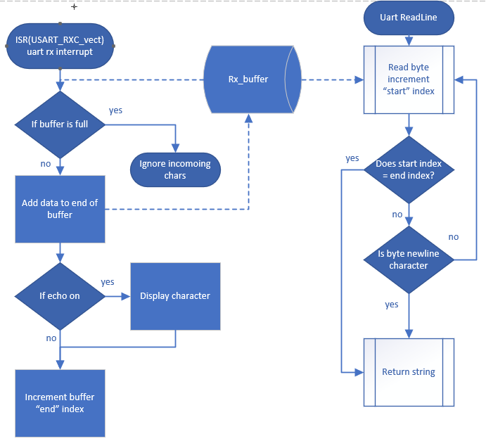
I started with a UART library for debugging. I would create an Rx circular buffer that would automatically save data till the processor was ready to process it. When a data byte was received the UART Rx interrupt would add the value to the buffer, then processor could then either read out a single byte, a number of bytes, or a whole line at its own leisure. On the Tx side I created a few functions to print numbers and send c style strings. Here is a very small flowchart explaining some of the Rx UART functionality.
In school I was told to intelligently comment your code. No one needs a comment that says:
//reads line from input
curr_line = input.readline();
Your comments should explain more abstract thoughts, non-intuitive code, and program flow, and I've been doing it ever since. But one thing I quickly learned while working in industry is even the best most thoughtful comments aren't the most efficient way to navigate a program, especially when you are coming back to a project you haven't touched in months or years. I still make lots of comments, but I always start new projects with a flow chart. It helps me plan how to code and think about corner cases before I've written a single line. As an added benefit, it's really easy to get your bearings in code by reading a flowchart rather than reading code line by line, especially after you haven't touched a project for months and need to do some "quick" maintenance. Depending on the code complexity I may include function names or even variables inside of the flowchart (so it's a little closer to UML), but the majority of the time an outline will suffice. During development I may change bits and pieces, everything I'm showing is based on the final implementation.
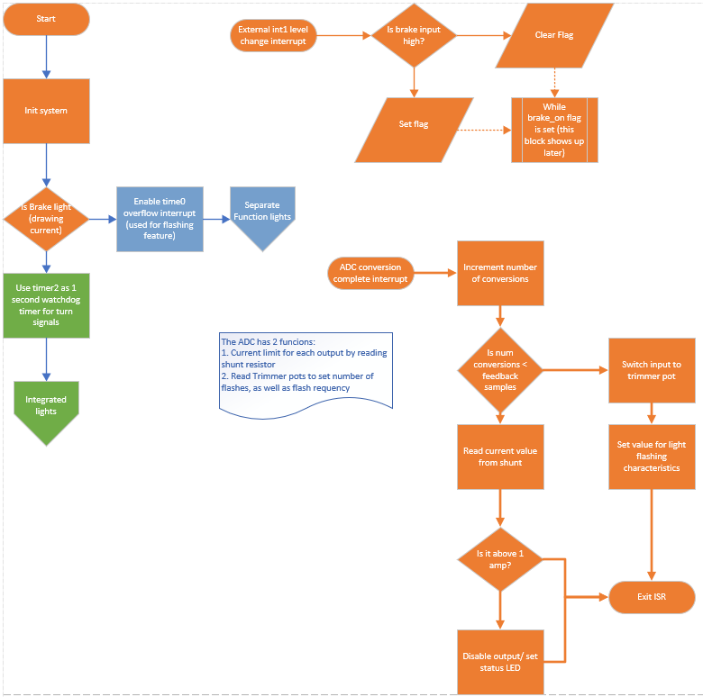
As you can see it is very high level. Something like "Init Sytem" block (upper left hand side) actually has many tasks, setting up GPIO, enabling timers, enabling interrupts, configuring ADC,setting up UART, initializing globals, etc. This small section shows the code that was common to both modes of operation.
I designed the system to have current protection and implemented it with two methods, one was in hardware (explained in part 1) and the other way was software using a shunt resistor/op-amp setup. The op-amp would amplify the shunt value to ~5V swing for the ADC. The board was designed to handle these high currents, but not for long periods of time, the software solution allowed me to disable the offending output and thus protect the system from damage.
Current monitoring was not the only task for the ADC, it also read some user adjustable 10kOhm trimmer potentiometers. These were used for the brake-light modulation feature, which as a quick refresher flashes the brake light a few times before solidly illuminating it. It makes you stand out more to other drivers which is always a plus on a motorcycle. These pots would adjust the number and frequency of the flashes. The atmega8 only has one ADC with multiple channels so I would take a measurement and move to the next channel and repeat. I decided the current protection was higher priority so I would only read the potentiometers once for every 20 current readings. Keeping the response time below 10ms.
The brake input is tied to an external interrupt as it is a bit more critical than turn signals. However the interrupt only set a flag for the brake lights, the flag was serviced by timer interrupts (more on that later). And with that you have an overview of the common features now we will look at the two modes in detail in a bit.
Separate function lights
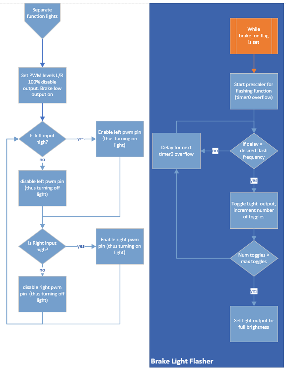
This mode of operation is fairly straight forward. There are 3 inputs: left turn signal, right turn signal, and brake; the system also has three outputs: left turn signal, right turn signal, and brake.
I simply set the turn signals to 100% duty cycle but disabled the output pins, I only enabled them when the turn signal should be on. This is because even at 0% duty cycle there is a tiny bit of illumination, by disabling the pin completely we solve this issue.
When the brake is not illuminated it shines at a dim glow (running-lights) but when the brakes are pressed I wanted full brightness. As mentioned before, the brake light flag was serviced by timer 0 in this mode. The timer overflow interrupt was triggered at around 1kHz, I then had a software prescaler on top of that to set the frequency of flashes for brake light modulation. After the desired number of flashes the light would illuminate solid, and that's that.
Integrated Lights

This mode is a bit more complicated. You still have the same 3 inputs: left turn signal, right turn signal, and brake but now you have only 2 outputs left light and right light. There are a few key points
- the lights should glow dimly (running lights) during "idle" times
- the lights should be full brightness during braking
- the lights should alternate between full brightness/off during turn signal (this creates more contrast than full brightness/running lights would)
Since one light must be a turn-signal and a brake this mode does not do brake light modulation, it could look confusing to other motorists. So when the brake is pressed the light shines brightly, very straight forward.
But if a turn signal is on I want that to over-ride the brake light. This was done using a "watchdog" type timer for the turn signal. Every time the signal went high a 1 second timer would get reset, if 1 second expired I knew the light could resume normal brake/running light duties.
The flow chart may look complicated, but it's essentially the same scheme twice for each of the two outputs.
Thoughts and last remarks
Well that all sounds great, but it makes a lot more sense with a video showing separate function mode on my bench
and on my motorcycle. Unfortunately, the video doesn't capture the high frequency flashes towards the end but you still get some idea of the modulator adjustment
Although the basic system is complete there are still a few more pieces for part 3. Including designing: the wiring harness, a case, and light modules for my luggage bags. You can view the full source code on my github page
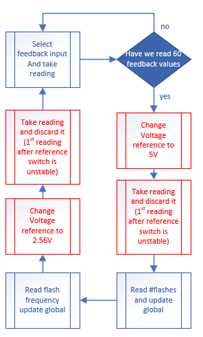
If you look at the code you may see a lot of "stuff" in the ADC ISR. As mentioned in part 1, this is actually the second revision of the PCB. One of the reasons for the redesign was the small shunt values in the original design. I thought I could alleviate this problem by modifying the ADC state machine, it would use the 5V reference for reading the trimmer potentiometers and the internal 2.56V reference for reading the current shunt resistors. Although this code worked well, the values were too low to read reliably. I increased the shunt size and added a non-inverting op-amp to each feedback circuit. This allowed me to keep the same 5V reference for all readings and measure currents more accurately. However, I still left the code in place, but these additional states are never entered.
The board respin also gave me a few opportunities to improve other pieces of functionality and code efficiency, For instant, I went from a RED status LED to a RGB LED that changes colors depending on the program flow and will shine RED during over-current conditions. I enjoyed creating this small status LED library particularly selecting the output color. The LED only supports 8 basic colors.
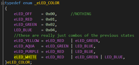
Each of the three RGB components was stored in a separate bit of the enum this foresight greatly simplified the code since all colors were permutations of 3 cases R,G, or B. An implementation using regular enum values (as seen below) would have had a separate if statement for each of the three colors and increased code size. It's always fun to think how a little bit of planning can yield more efficient coding.

There is also a lot of extra code in the "main" function. I developed some small debugging routines to verify the functionality of each of the peripherals: UART, ADC, PWM, Timers, etc. I planned on having the code in final fw, but it simply took up too much code space. I eventually commented it out but left it in should I ever need to tweak the system in the future.


Comments