Tilting Phone Stand
- Andrew Asuelime
- Mar 10, 2019
- 5 min read
I had recently purchased a second hand 3D printer and was eager for my first print from my very own machine! I have a few ideas for some upcoming projects. Some a little more involved than others, but I wanted to start with something fairly basic. I wanted a project that could test my machine and see what it could do, but at the same time, be relatively low stakes. I'd like to learn my machine in a relaxed setting, with an easy project. So I decided to make a phone holder for my sister.
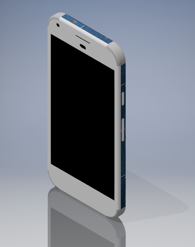
Initially, I thought I would make a tight fitting case, with a leg on the back. She could slide her phone in and the leg would support her device in landscape or portrait mode. I would use ball detents to lock the rotation between the two modes. I would create a pivot point and snap the pieces together. Then it would have adjustable tilt. I thought I could use a slider system with small notches cut out to hold the phone at a few specific angles. Naturally, I wanted the phone and all buttons to be usable. This would require a fairly accurate representation of the phone so I grabbed my ruler and calipers and got to work on the phone model.
I mentioned my idea to a friend and their response was that stands were cheap on amazon, why not buy one? Well I wasn't going to do that as it would defeat the purpose of the project, but their comment did make me rethink my design. I decided to use a much simpler universal design. It would work with any phone and you could even charge your device while using it! Sounded like a win in my book.
DESIGN
The stand would be made of 3 basic components:
Base
Cradle
Tilting mechanism


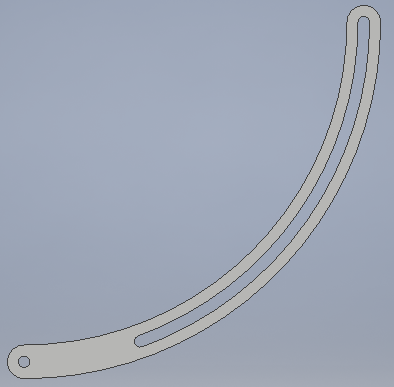


The parts themselves were fairly straight forward. The base was a simple wedge with hinges on top. I would use these hinges to connect it to the tilting cradle. The cradle was a little wider than the phone with a hole in the bottom. This way you could still charge your phone in the stand. Lastly, I hollowed out the pieces to use a bit less filament while still maintaining rigidity. I spend some time making the cradle aesthetically pleasing, but quickly added slots to the base without paying much attention to the overall appearance. The tilting mechanism was also very simple. It was an arc that would connect the cradle to the base. You would adjust the angle with a small nut. The nut would screw onto one of two threaded posts on the base. The cradle would also have a post on each side to hold the other end of the arc. Making two mounting points was a great decision, but more on that later...
THE PRINT
This being my first self-designed print I wasn't sure how things would go. I added chamfers to my edges and a few "small" features to really see how well this machine would work. I started out with the base, it had more material than all the other parts combined. I added support structure as I was unsure about the overhang and chose what I thought was a conservative 60mm/s feed rate with 0.1mm layer height. My design had around a 60 degree bend, which should've printed without issues, but it was a new printer and i was worried so I added a few supports. turns out they weren't needed, in fact they caused quite a few issues! The supports weren't all too stable and ended up making a mess of tangled plastic. Ruining one of the slots. Overall the part was still acceptable, So I kept it as it was, this was one of the benefits of a low-stakes project. It didn't matter if there were a few blemishes here and there.
The other parts were pretty uneventful. After looking more closely at my printer specs I saw it could print up to 200mm/s with normal speeds of 100! I really pushed the speed of the printer, 185mm/s for the nut, 150mm/s on the arc and 125mm/s on the cradle. I also experimented with layer height (.2 and .3) and infill (20%-45%), just to get more familiar with the printer and strength of the PLA. I was really worried the cradle would have layering issues on the top especially with the high travel speed, But it all turned out really great! The parts required some mild sanding and I melted some "stranding" with the heatgun, but overall, a successful first print.
FINISHING AND ASSEMBLY
And now the final steps. Putting everything together; now THIS was truly an exercise in creativity! Where to begin...
THE HINGES
Well, they printed decently, originally, I planned on using some scraps of 1.75mm diameter PLA as the center pin, unfortunately, there was quite a bit of shrinkage in the holes and I had to drill them out. My standard drill bit kit was in need of replacement, most of my smaller bits had broken, and of course the broken bits were the exact ones I needed. It's probably time I replaced them, but what was I to do in the meantime? I remembered I purchased a micro-drill set a few years ago. They were originally meant to clean motorcycle carburetors, but since then I've used them to drill PCB and now to clean my prints. That was one issue solved, next, the hinges interfered with each other just a bit. I guess I'd over estimated how precisely I could print, I needed to shave down the spaces in between the hinge posts so the two parts would fit. Second problem solved, onto number three: the holes were still much too small for the PLA rod I had envisioned. I looked around and found some 18ga steel wire that actually fit perfectly, crisis averted.


You'll notice one of the broken slots on the base.
THE TILTING MECHANISM
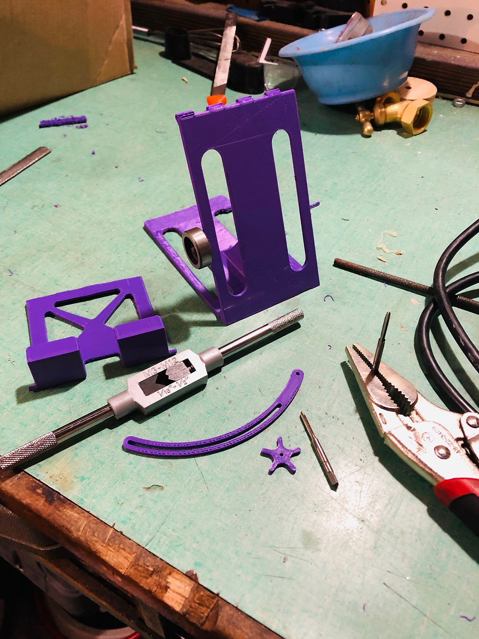
These were supposed to be M3 sized, the operative word being "supposed." I was going to tap the nut and cut the two posts on the base. Remember what I said in the beginning about having two mounting options? It turned out to be an incredibly lucrative decision as one of the posts warped on cooling, so I was unable to cut threads in it properly, no matter, I still had the other side.


ASSEMBLY
Problem number one, the tilting mechanism didn't work. My tap was unable to thread the entire post so even fully screwed in the nut didn't put enough pressure on the adjuster to lock the tilting mechanism. I originally had each part thrice as thick but decided at the last minute to reduce the thickness to save some filament and lower the print time, oops. I looked around and found a small plastic washer to remedy the issue.
Cool, one more problem solved, but now... Just kidding! Luckily that was it! Everything went together and I was really surprised how well it matched my model. It looked pretty good, take a look for yourself.

LESSONS LEARNED
I learned a LOT in this fairly simple design:
How important it is to design for printing errors
Be more realistic with hinge tolerances, since they do deform. I would clear out more space between the hinges to save post processing work
I can use 18ga wire for any future hinges!
How slots can affect the overall stability of a part
How quickly I can print and still get decent results
Small tricks to speed up the modeling process
The need to adapt!!!
I look forward to applying all this knowledge in my next projects


Comments